heikki.juva.lu
Display case for my projects and writeups. I mostly work on InfoSec, hardware hacking and electronics.
Project maintained by Zokol Hosted on GitHub Pages — Theme by mattgraham
Hardware Hacking 101
Here is a short intro of how to get started with hardware hacking and what tools you might need.
Koteco
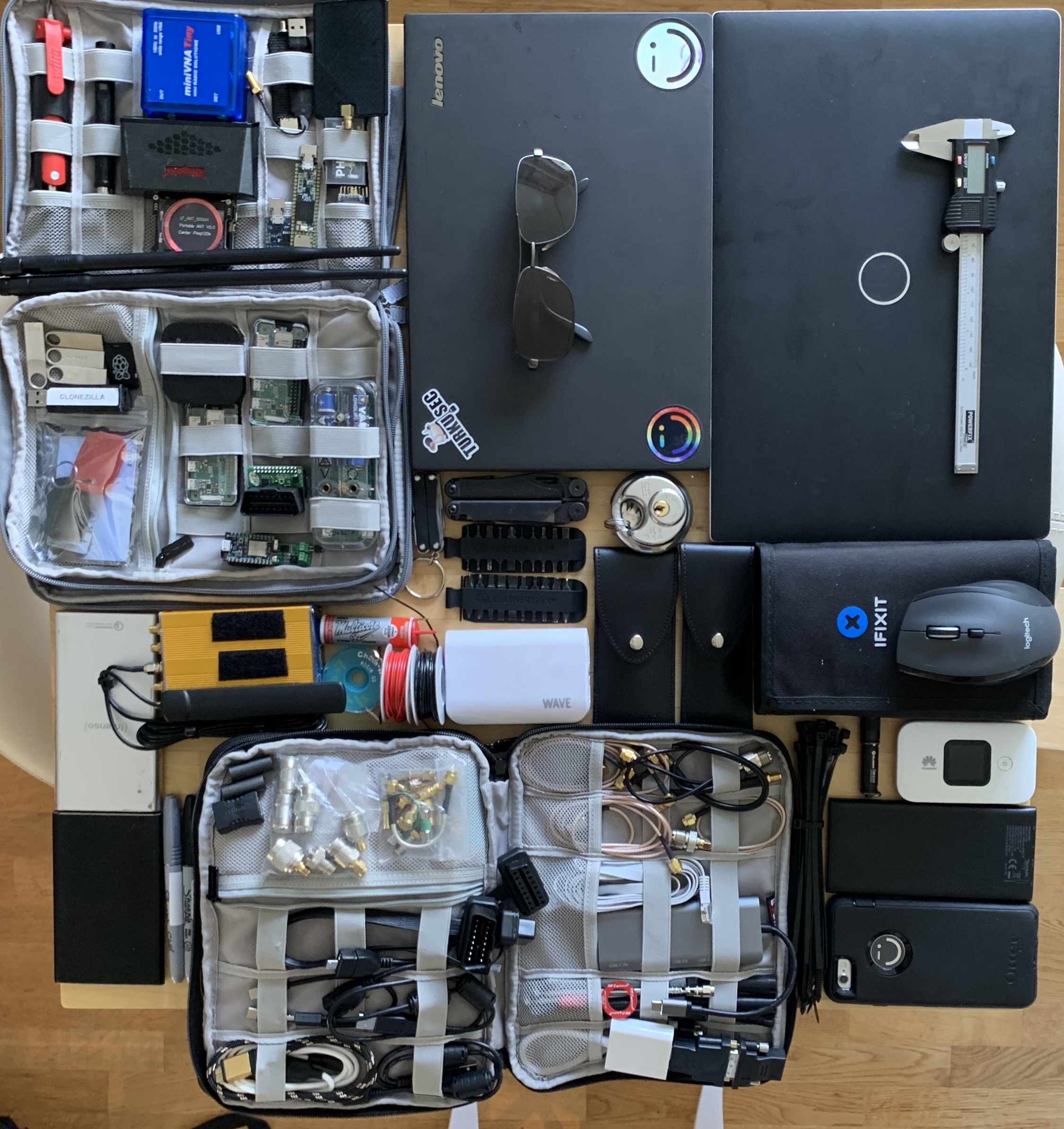
I have been working with our team to design toolkits, from hackers to hackers.
Our goal is to utilize our own experience and select the best tools for each job.
These are the same tools we carry, organized in kits that make preparation for the next trip much easier.
We are currently in field testing phase, I will write and tweet about it as soon as the kits are published.
Training
Want to learn more and get real hands-on experience in hardware hacking?
Sign up to my hardware hacking course.
Safety
MOST IMPORTANT STUFF
- When operating with electricity, you should always think about what you are doing.
- Easy way to ruin your day (and your multimeter) is to accidentally measure resistance, instead of voltage, of 240VAC wall socket.
-
If you are not sure, take a break, measure again and ask a fellow hacker to check your connections.
- Plan your actions so that you never have to touch or modify live circuits.
- When measuring live circuits, if possible, connect and disconnect probes only when circuit is not live.
Live circuitin this context means that the device is connected to energy source (battery, mains, etc.)
- Remember that unplugged device can still contain deadly potential, stored by the capacitance of various components.
- Larger capacitors should always be discharged in a controlled manner, for example using a suitable high-power resistor.
- Identify the dangerous parts of a circuit and make sure that you won’t be able to accidentally touch them.
/MOST IMPORTANT STUFF
Intro
Hacking in general can be thought as changing the behaviour of a target in a way that the original author did not intend to happen.
Examples of this can be seen in everyday life; using a knife as a fork or a Raspberry Pi as DHCP-server for large enterprise network. It’s mostly about getting the job done with what you have. It may be unreliable or non-sustaining solution, but it’s good mindset to have.
The term “hacking” is usually referring to hacking against software targets, like web services and applications. This is popular, mostly due to how commonly software is controlling systems, as well as the relatively low cost of hacking software targets.
For example; analyzing a software component usually just requires a computer and few open source software tools. These tools are usually free, quite reliable and easy to get.
Hardware hacking refers to modifying the behaviour and/or inspecting the workings of physical electronic devices. Hardware targets almost always run software. The rest of the cases are either completely discrete or analog circuits, where the operation logic is determined by individual semiconductors placed in certain way. Similar special case is an FPGA-based solution that uses semiconductors to form circuit, without any soft-core IP runnign software. Hacking these circuits requires deeper understanding of electronics and analog circuits, but still the same toolkit works for them.
In most cases, hardware hacking can be similar to hacking a web server, but instead of being able to SSH directly from your laptop to a server in Ireland, you need to consider the physical interfaces and how to talk with the device.
This also means that in most cases, a hardware hacking toolkit is simply used to indentify, enumerate and bypass the hardware-layer, to gain access to the software-layer of the system.
Blackbox
So, you have a blackbox in front of you?
A device you know nothing about.
It just has some connectors on the side, a screen and few buttons.
Step 1. Start with external interfaces
To gain more knowledge, you can start by looking for an interface that is easy to use and easy to access, like USB, Ethernet or HDMI. Tooltip: To be able to connect to the device, you want to carry few common cables with you.
You might find an Ethernet-port. It’s likely that you can gain more insight of the device by connecting it to a network. Tooltip: For inspecting network traffic, pack a few ethernet cables (short and long), as well as an Ethernet-tap to inspect the traffic
Remember to try resetting the device after connecting to the interfaces. It’s common that during boot-process the device performs operations and communicates with peripherals more actively than in standby.
Step 2. Teardown
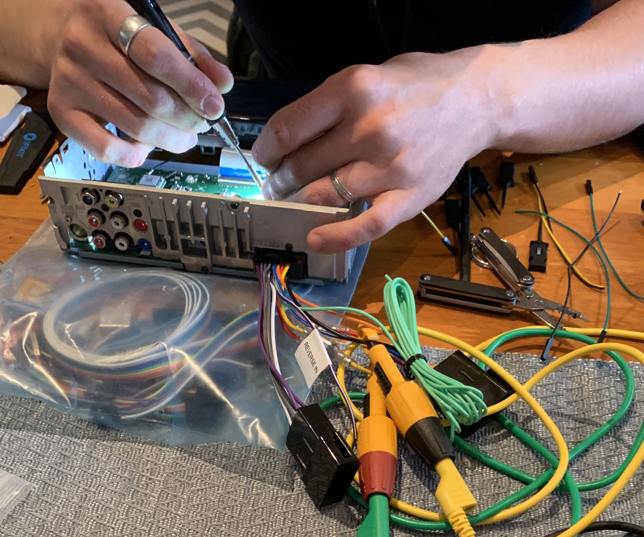
Usually the more interesting interfaces are hidden inside, on the PCB of the device. This is due to how the devices are manufactured.
The process of building a device involves testing. Testing an electronic device in production requires some amount of physical interfaces. These interfaces commonly offer quite good access to the software-layer, as they are used for programming and debugging the device.
It’s common to find serial-interfaces on the PCB, usually offering root-priviledge without password-prompt. Reasoning behind this is that testing in production is costly, so every extra step is often bypassed, including user login.
To gain access to these interfaces you need some tools to take the device apart safely.
Tooltip: Armed with iFixit Toolkit Pro, pliers and sidecutters, you will render the device into pieces quite quickly
Step 3. Identifying pinouts
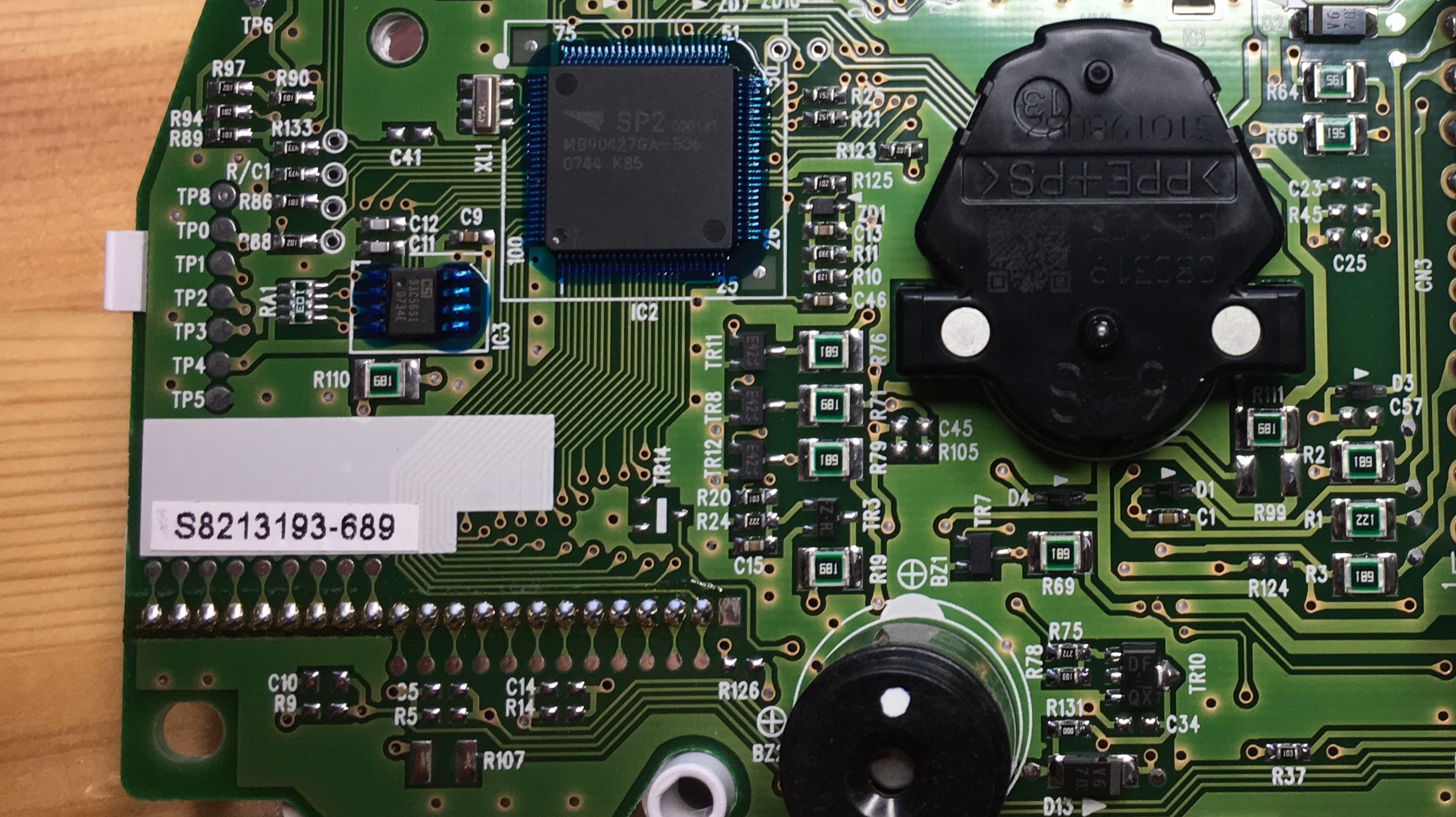
PCB will most likely contain tens if not hunderds of testpoints, those round unconnected pads, usually with text “TP” and a number next to it.
These pads are used during manufacturing, to test for voltages and signals, verifying that the device operates correctly.
From these pads, you can also find good attack vectors, like a serial terminal or communication bus containing an EEPROM.
Usually testpads have no indication of their type, so it coudl be connected to 5V power bus or SPI MOSI-line.
To find the nature of the testpoint, you have some options:
-
Visual inspection; thicker traces and large copper areas are usually connected to power or ground.
-
Measure resistance; Power down the device and measure resistance between testpoint and known ground (e.g. usb-connector body). If resistance is close to 0 Ohms, you know that the pad is ground.
-
Measure voltage; Be careful not to cause shorts while measuring. While device is powered, measure voltage between testpoint and known ground. If voltage is 5V, 3.3V, or 1.8V, it may be a power- or logic-trace. If you measure negative voltage or over 5V, it may be a differential signal.
-
Probe signals; Using an oscilloscope, you can identify the testpoints that carry digital signals. Note the signal voltages and determine if you need special hardware to access the signal. For example; differential signals require dedicated component to transform the signal levels. (e.g. -12V - 12V to 0 - 5V)
-
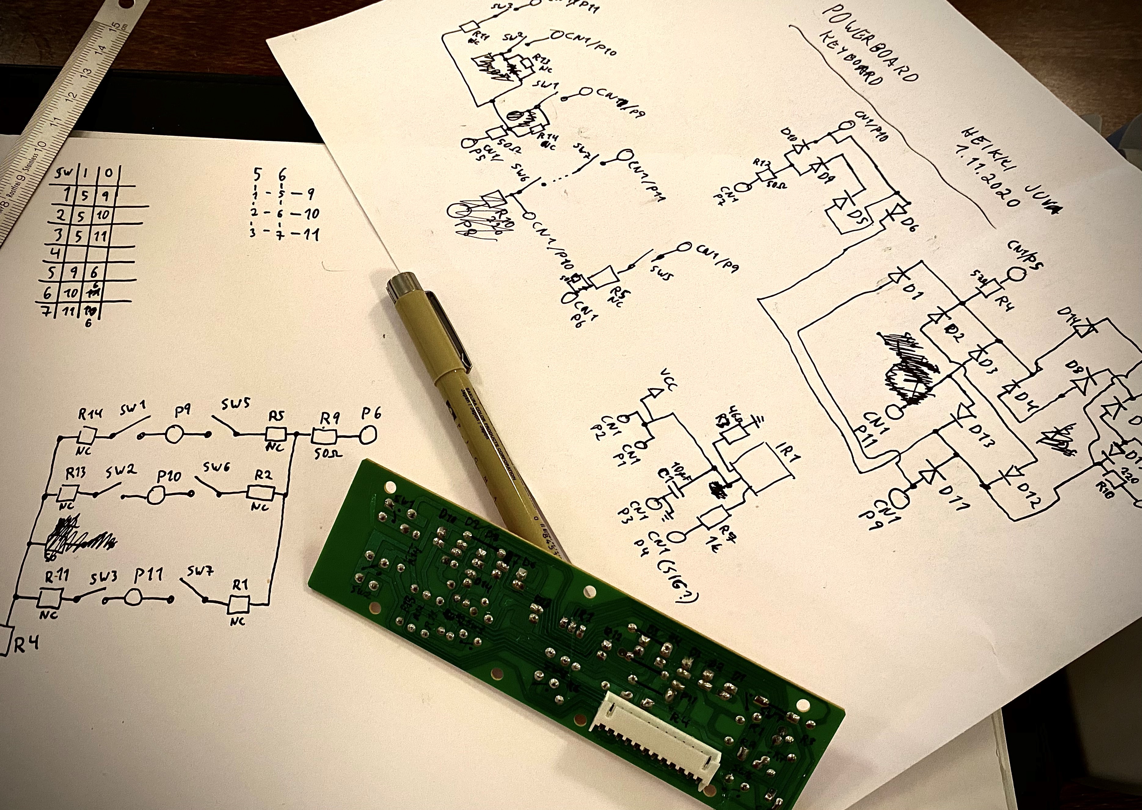
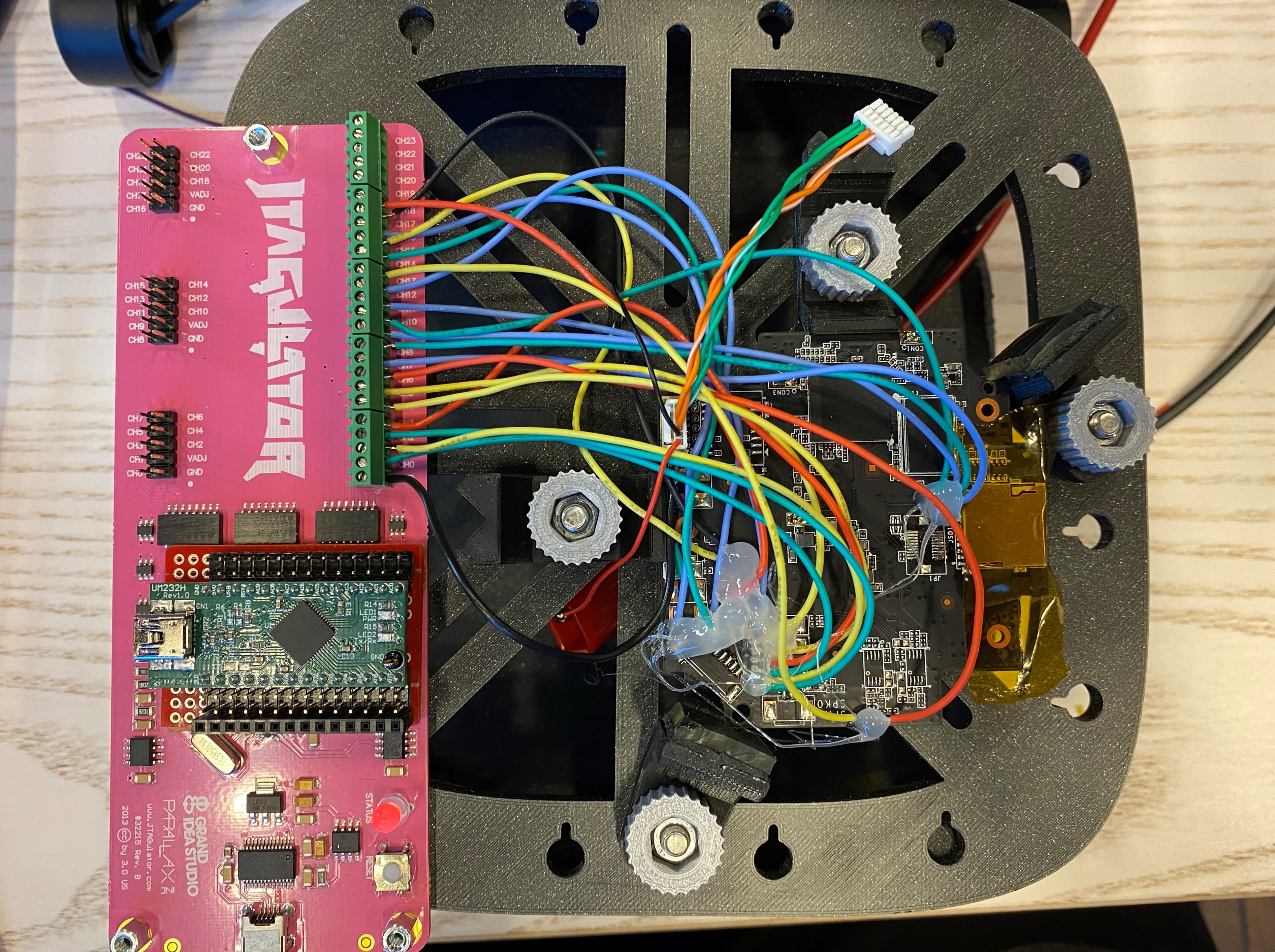
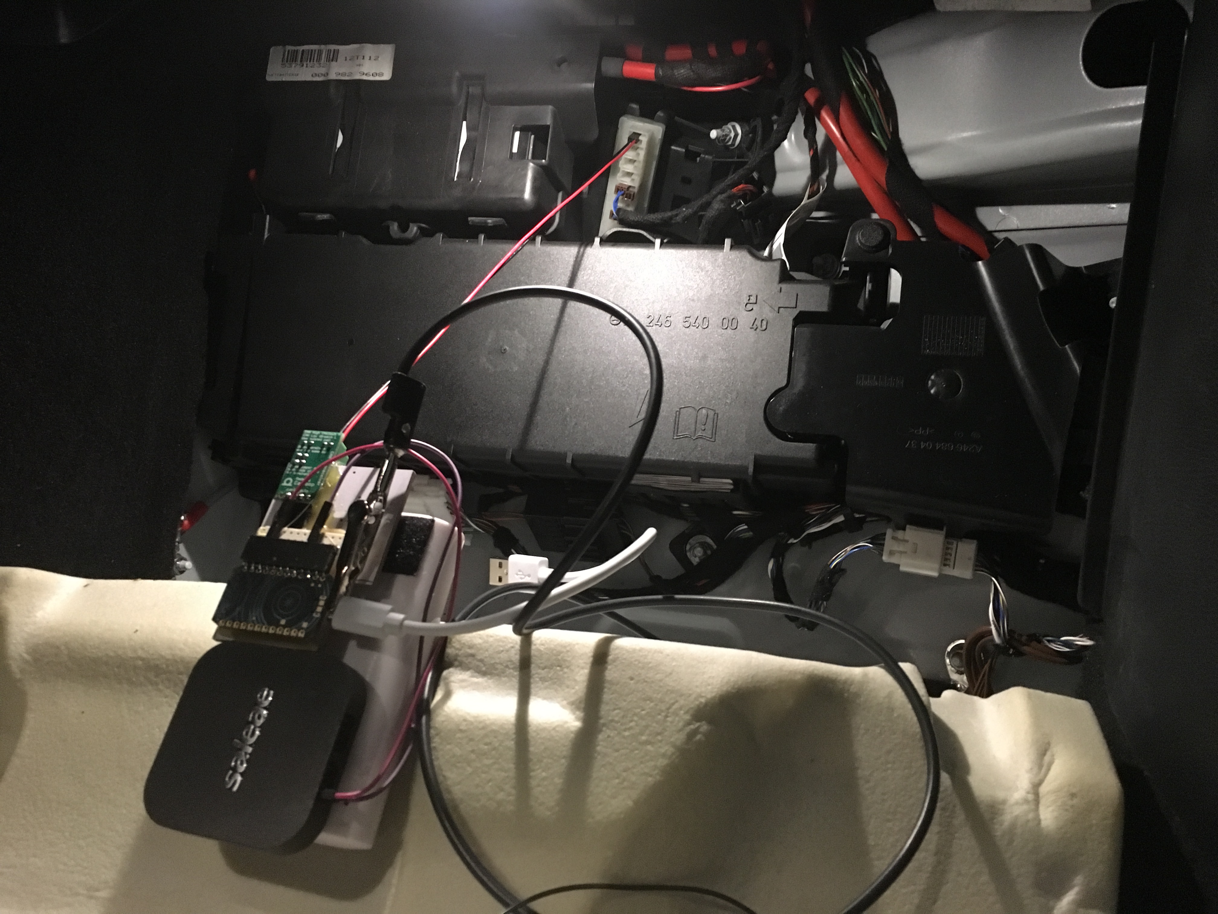
Analyze signals; After identifying the testpoints that are safe to connect to, solder wires to these testpads and connect them to JTAGulator or logic analyzer.
Take notes during this process and write down the testpoint numbers and measurements from each testpoint.
As a result you should gain enough knowledge to identify the structure of the device and how to talk with it.
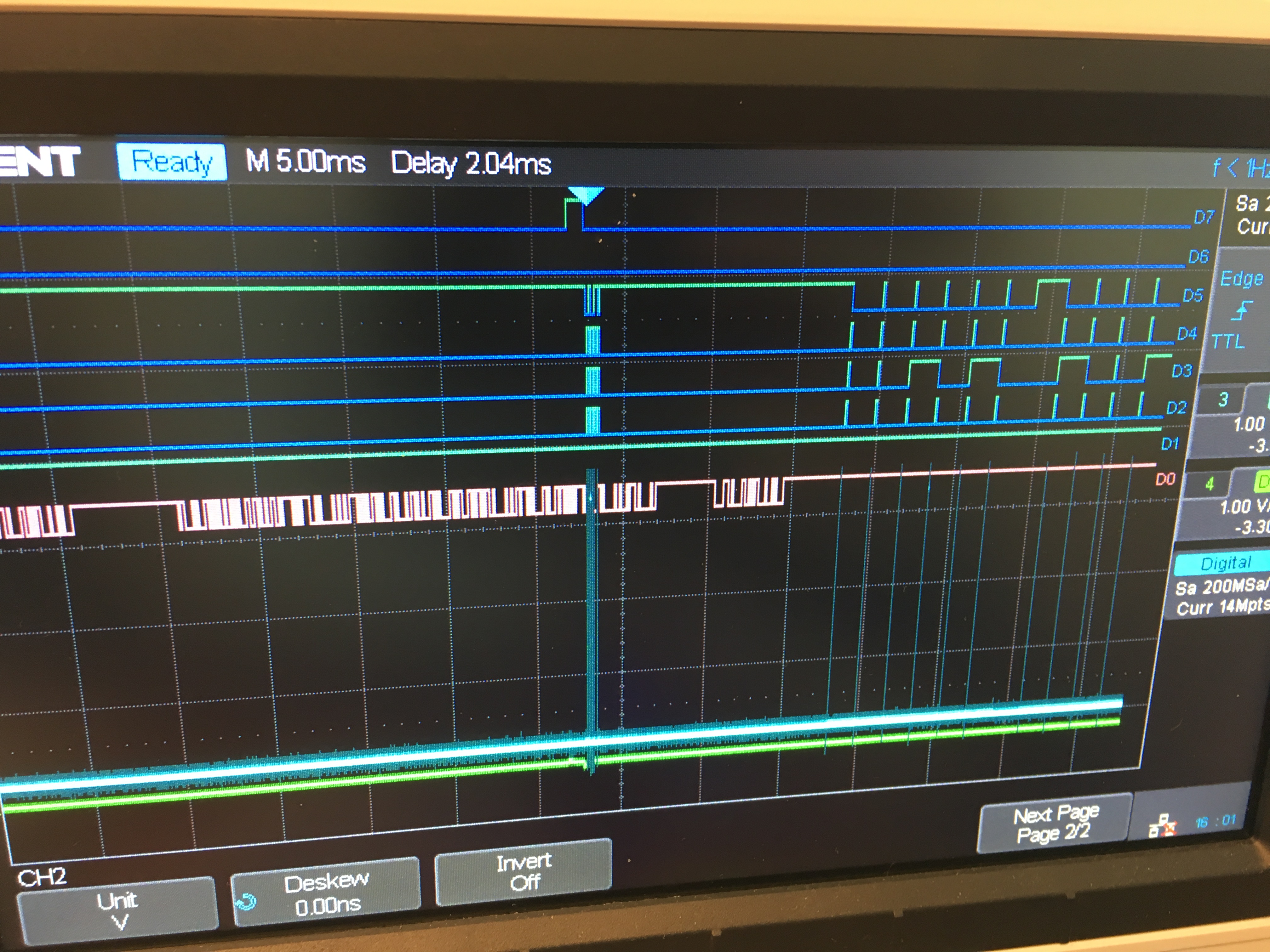
Tooltip: To inspect signals, oscilloscope is nice to have. For low-voltage applications a logic analyzer with analog-measurement is sometimes even better.
Tooltip: JTAGulator saves a lot of time identifying serial- and JTAG-signals. Alternatively the signals can be manually identified via logic analyzer capture.
Tooltip: Soldering iron and multi-color assortment of 24AWG silicon wire is often nice to have to make solid connections to the PCB
Step 4. Enumeration
Serial
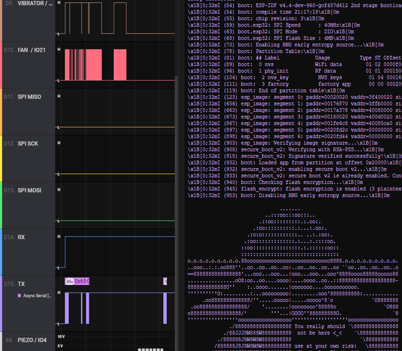
After finding a serial-port, it’s good practice to record the traffic while resetting the device. Usually the boot-message tells you a lot about the device and the software it is running.
I2C
If you uncover a I2C-bus, it may be good idea to record traffic and analyze it in logic analyzer.
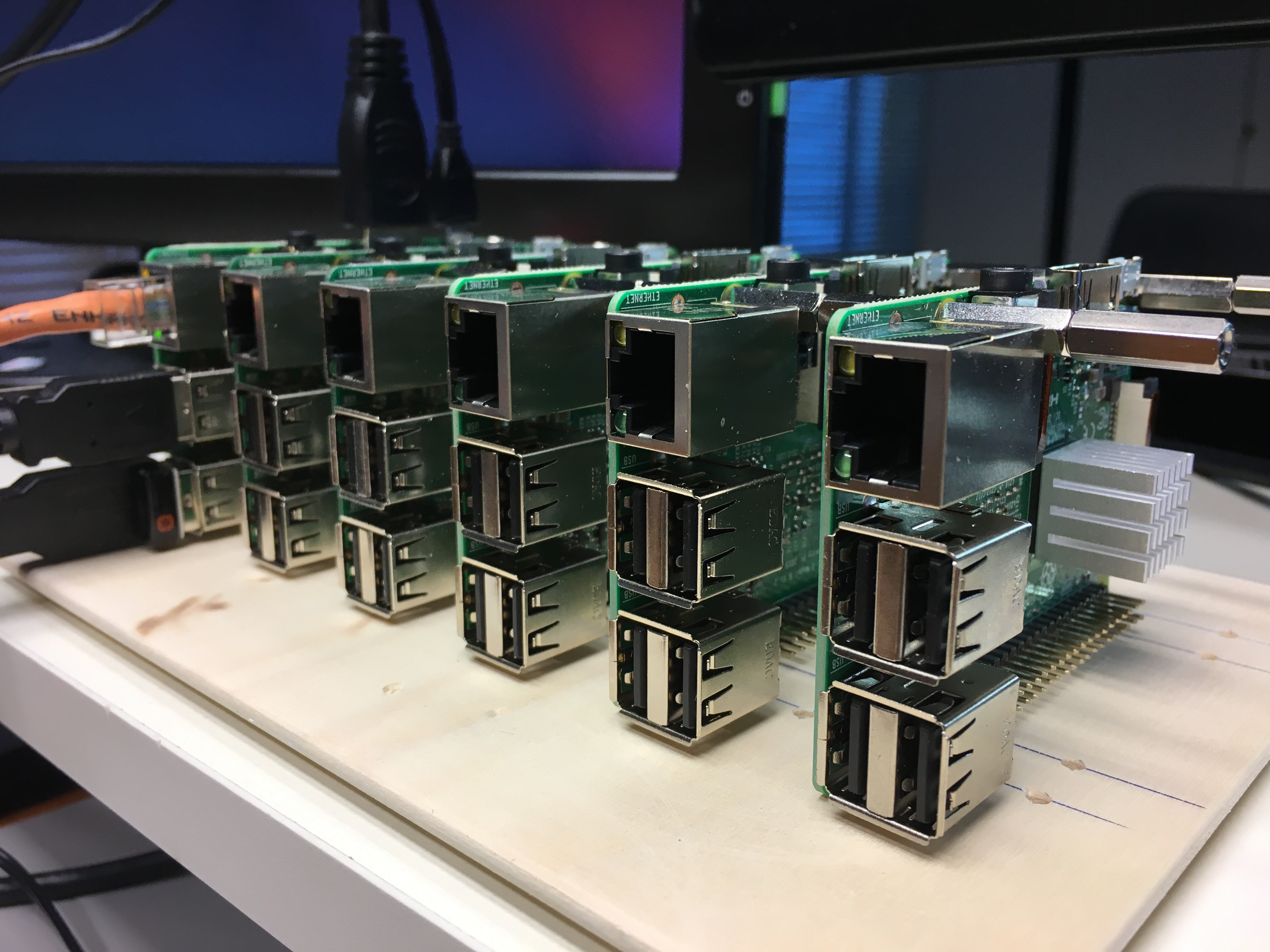
If no traffic is present, you can try to connect a Raspberry Pi onto the bus and run i2cdetect -y 1 to see if the bus has any I2C-devices connected to it. This command will show you a listing of device addresses on the bus.
Tooltip: For I2C EEPROMs, often the best tool for dumping the contents is an Raspberry Pi
SPI
For SPI-bus, it’s common to have it between the main processor and flash-memory, or other high-bandwidth chip.
To analyze this communication, just record it with logic analyzer and decode the traffic.
Raspberry Pi can be used to interface with SPI-bus, for example using spidev.
CAN
CAN-bus requires some hardware to make the signal translation, which can then be decoded using an logic analyzer. Remember to record the traffic after reset, to see what the device sends to CAN-bus during boot-up.
There are also good linux-based tools to inspect and enumerate CAN-bus networks.
Advanced measures
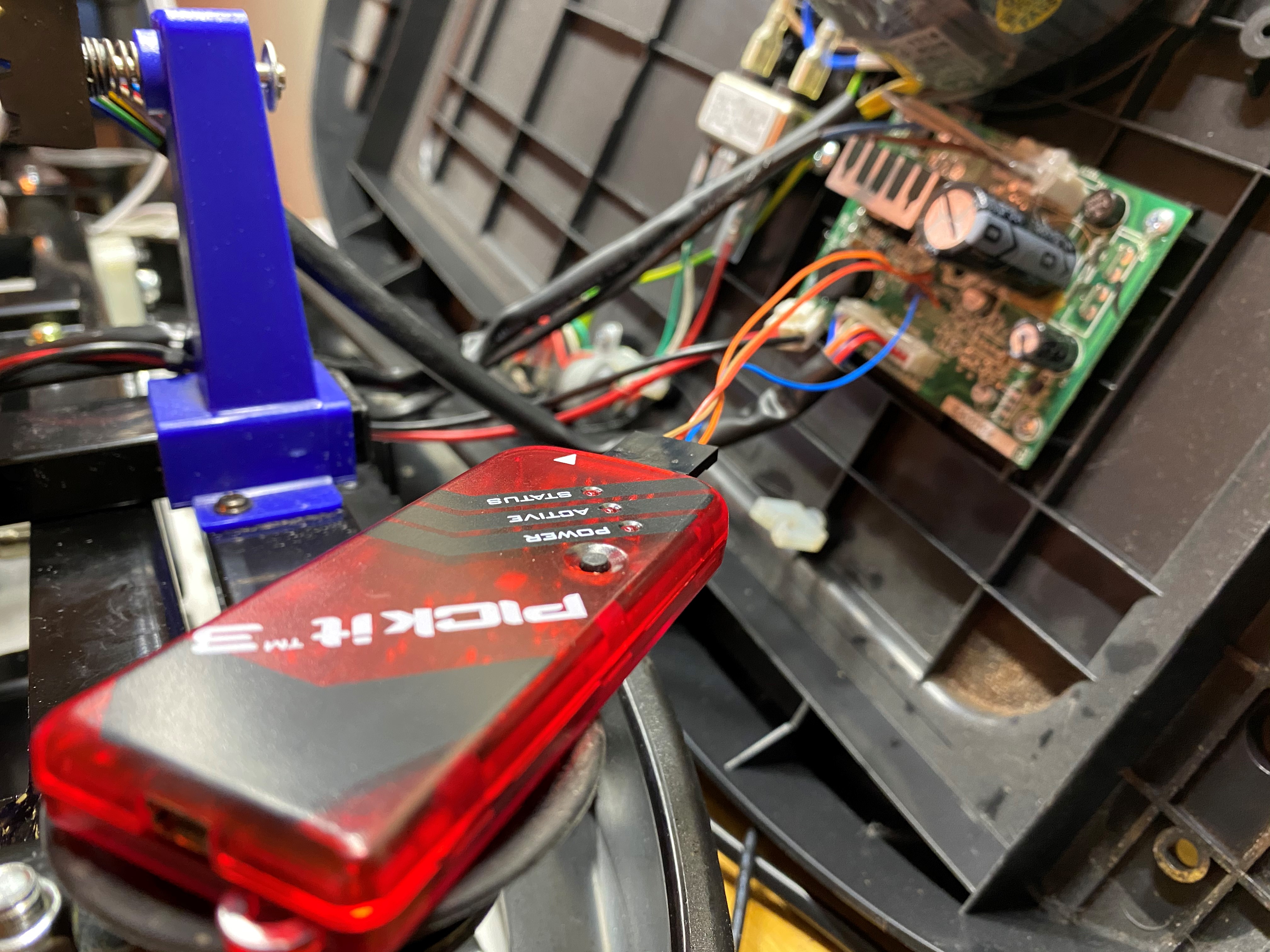
Next steps for hardware-side would be dumping firmware from processor, side-channel attacks, dumping memory from flash chips, etc.
These steps require more specific hardware, most often outside of hobbyist budget and very specific tools that only work for certain devices, so I will leave those topics for another post.
Hardware Hacking Toolkit contents
Summarizing the toolkit from the above chapters:
- Pen, paper and camera/smartphone
- Common USB-, HDMI- and Ethernet-cables
- Multimeter or two with good probes
- USB-serial adapter
- Raspberry Pi
- iFixit Pro Tech Toolkit, pliers and sidecutters
- Jumper wires with dupont-connectors and multi-threaded silicon wire
- Soldering iron and 0.4mm solder
- Logic Analyzer (Saleae Logic 8 & JTAGulator)
- Oscilloscope